

I was asked to give a presentation concerning building sculptures at the 1000steine-Land 2005 in Berlin. Since I receive a lot of e-mails concerning this topic, I would like to give an insight on the speech here.
As a child, I was often amazed by the big sculptures displayed in the window of a toy store and I always wanted to build something like that on my own. Quite a few years later, I was finally able to do so.
Rene Hoffmeister announced my speech in the 1000steine.de forum very appositely: "Again and again sculptures made of Lego let people wonder: How are they built? Building plan, rasterized paper or build from scratch? How does one get the right proportions, how are geometrical shapes made? Tobias will present a quick overview on how to build a sculpture in his presentation."
In fact, a few Lego-fans do indeed build sculptures without previous planning. But for beginners, this may be a bit difficult since it requires quite a bit of experience. On this page, a few techniques are introduced that will show you how to develop an idea all the way to an almost perfect building instruction.
 |
 |
 |
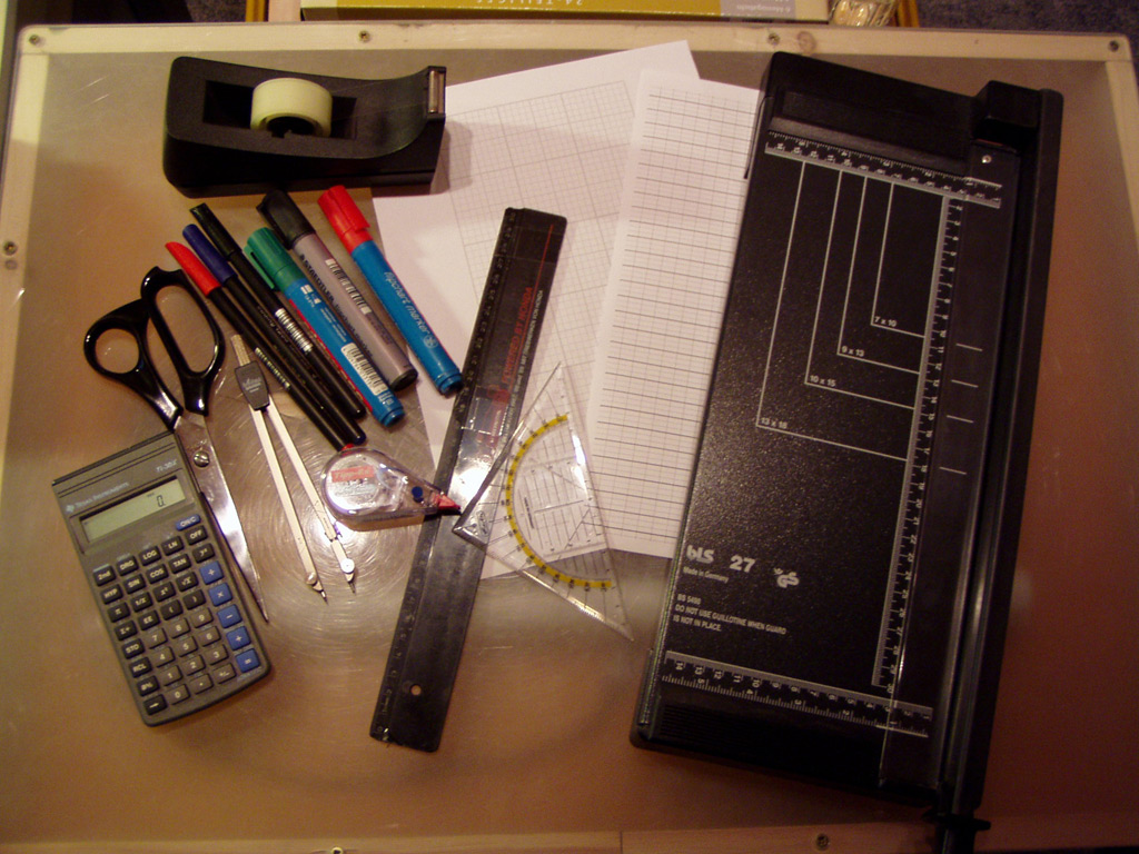
In order to be well prepared, you'll need a few important tools:
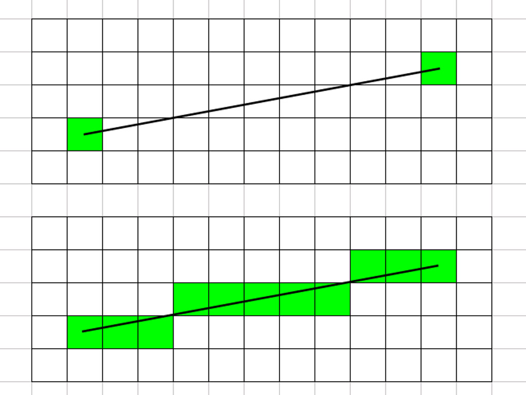
A few theoretical notes before the first example is introduced: Whenever drawings are created throughout this tutorial, the most important goal is to find the best approximation of a given line on squared or brick paper. In information technology, this is called "rasterizing of lines". There are different approaches and algorithms to solve this problem. One example is the Bresenham-algorithm (Wikipedia: Bresenham-algorithm). These are used to display lines (circles, etc.) on a computer screen. A screen consists of a finite number of pixels. Every geometrical shape is made up of an infinite number of pixels though. An accurate display is thus not possible. The geometrical shape is to be displayed by those pixels located closest to the ideal line. This problem is very similar to the one appearing when constructing sculptures from Lego, every brick resembles a pixel. The goal is to find the best approximation to an ideal line using bricks. The Bresenham-algorithm uses a built-in error correction. For our purpose, this is not necessary. The aim is to always choose the pixel, whose center is closest to the ideal line!
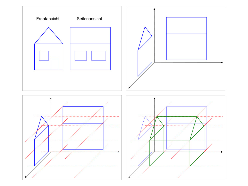
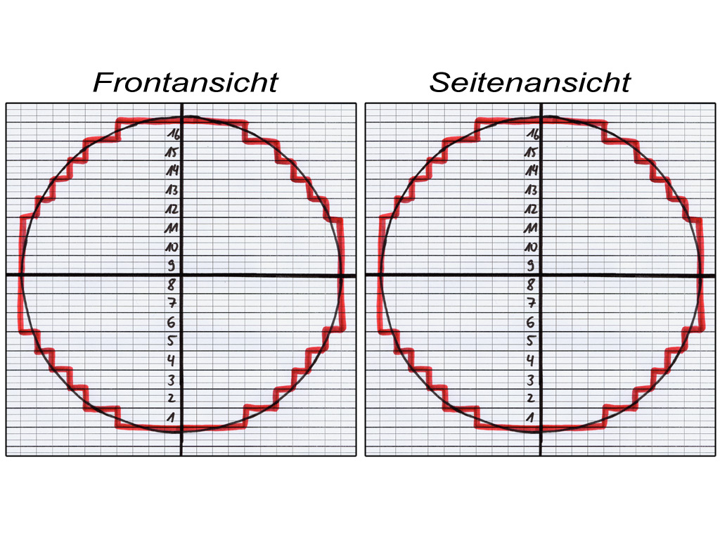
The first out of two examples introduced in this tutorial is a sphere. Spheres are needed again and again when building with Lego bricks. The approach remains the same and is always equally easy: As you can see from the picture showing the house, you will always need a front and a side view to create a three-dimensional object. The third dimension are horizontal cross-sections throughout the object.
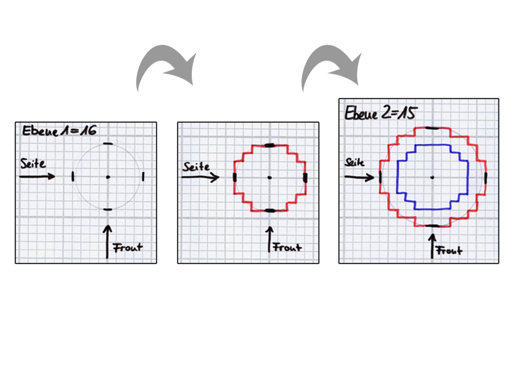
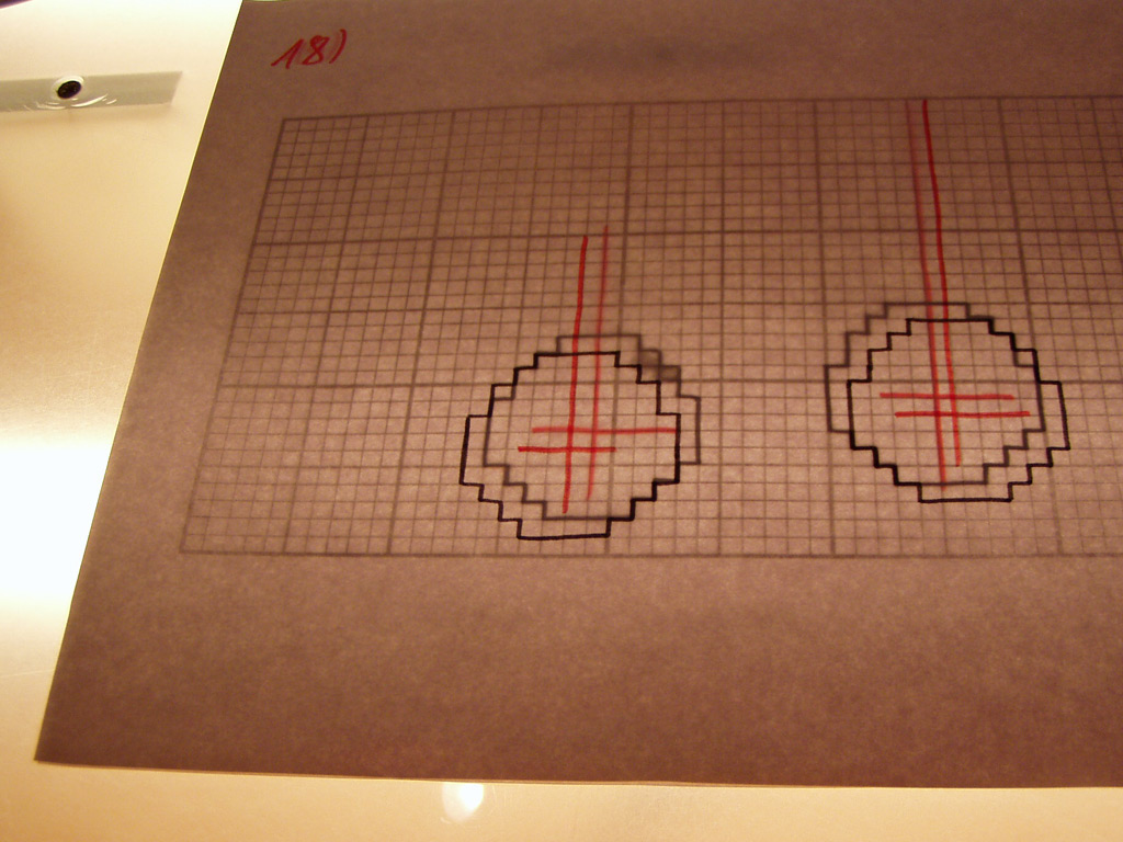
To build a sphere with a diameter of 20 studs, you will need a front and a side view, which are identical when creating a sphere. Use a compass to draw a circle set up with a radius of 10 studs on brick paper. Now have a look at the grid to find the best approximation to the ideal line of the circle. Using the front and side view, each brick layer can now be drawn on squared paper. The third graphic shows the first layer (which is identical to layer #16). In the beginning, the top view of the center of the brick layer is drawn. The front view shows it to extend for four studs to the top and bottom respectively. The side view also shows an extension of four studs to the right and four studs to the left. This information is now drawn into the top view of brick layer #1 and connected to the ideal line. Afterwards, the outer line of this layer (as the best approximation to the ideal line) is drawn over the ideal line on the grid of the paper. All other brick layers are approached respectively. To simplify the construction of the sphere, the outer line of the underlying brick layer is copied into the top view of each new layer.
 |
 |
 |
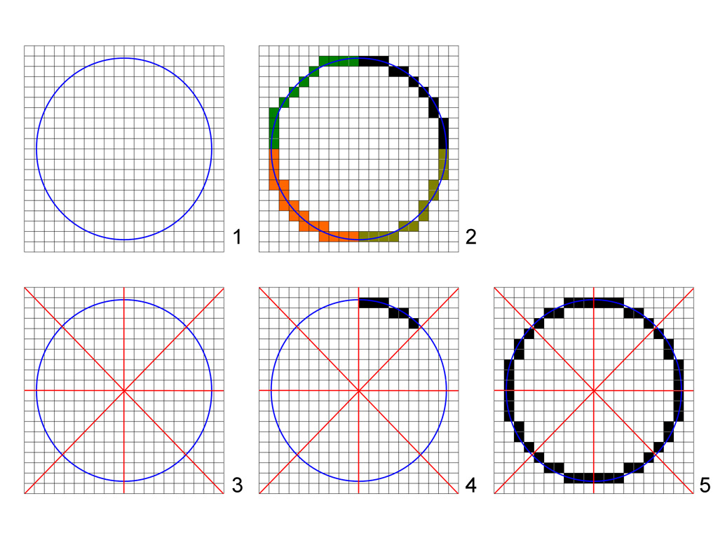
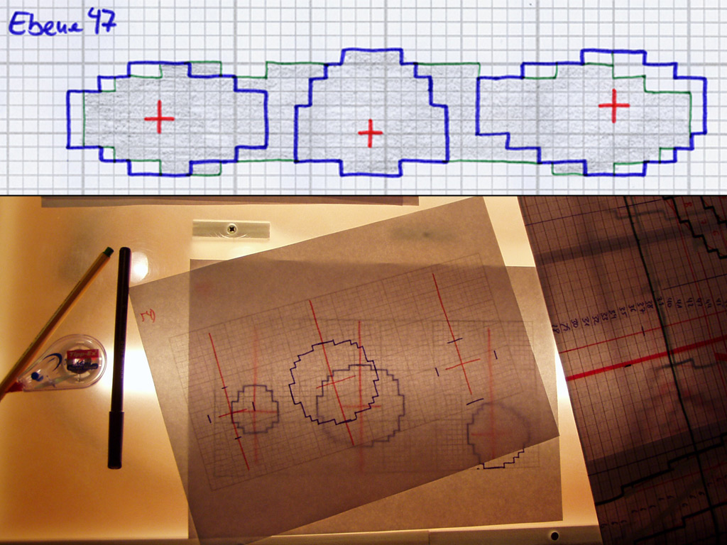
When looking for the best approximation, it is always useful to use any possible symmetry. The circle #2 in the picture below shows different approximations, who, as a whole, do not make up a nice circle. In this case, it is best to work with eighth of a circle. Thus, the circle is broken down into eight sections (comp. #3). As the circles #4 and #5 show, an approximation to one of these sections can now be drawn and transferred to the remaining sections.
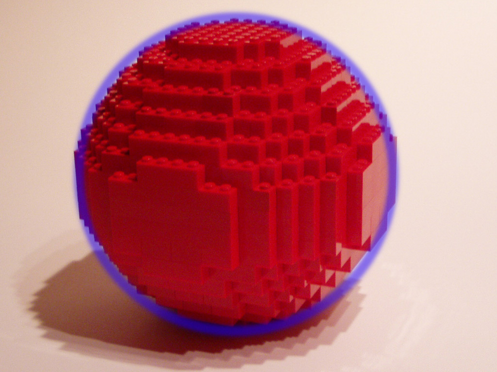
When the sphere is constructed from bricks, it is useful to draw the used sizes of bricks into the top view. This way, the sphere can be built over and over again without having to generate it in MLCad or a similar software. When building a closed object, the first and last three layers should not contain any vacancies. The remaining layers can be constructed from bricks following the contours with an adequate thickness. This way, an almost perfect sphere with a hollow interior is built. Bricks overlapping each other with an angle of 90° provide the best stability. Should the interior cavity be too big, additional bricks can always be added.
 |
 |
 |
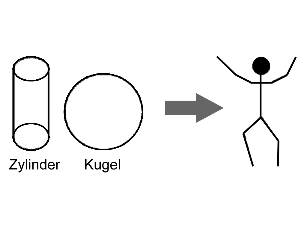
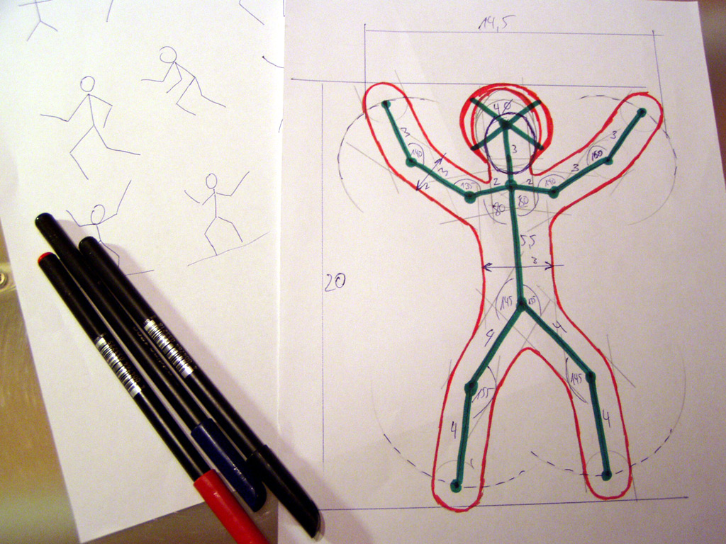
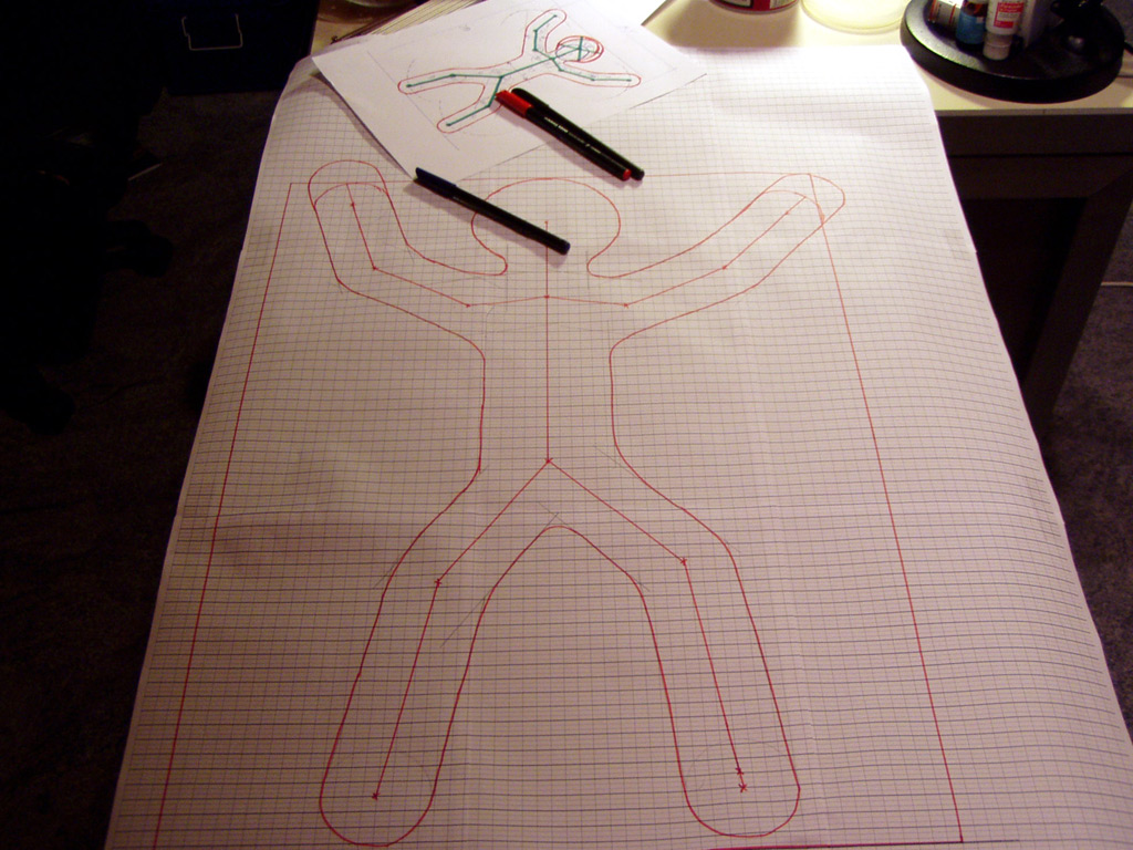
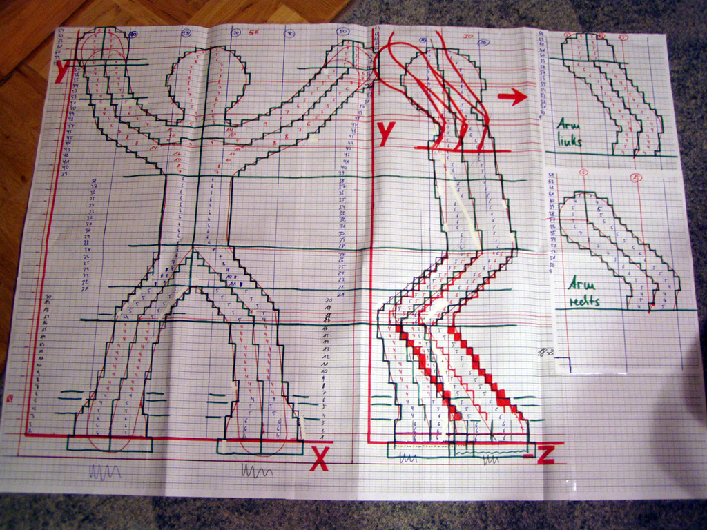
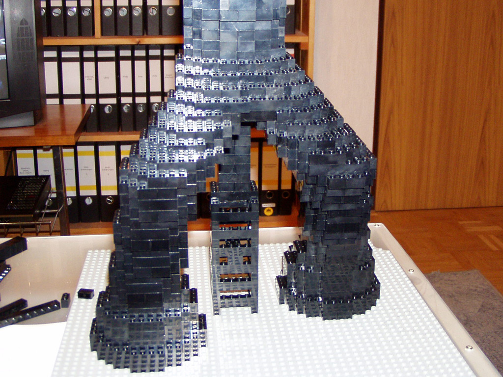
The second example is the Dynamic Man. It is a fairly complex sculpture consisting of simple geometrical shapes, such as cylinders and spheres. Here, too, a front and a side view are needed. After drawing a "skeleton" and deciding upon the diameter of individual body parts, a contour of the sculpture can be drawn. Subsequently, it is transferred to brick paper according to scale to complete the front view.
 |
 |
 |
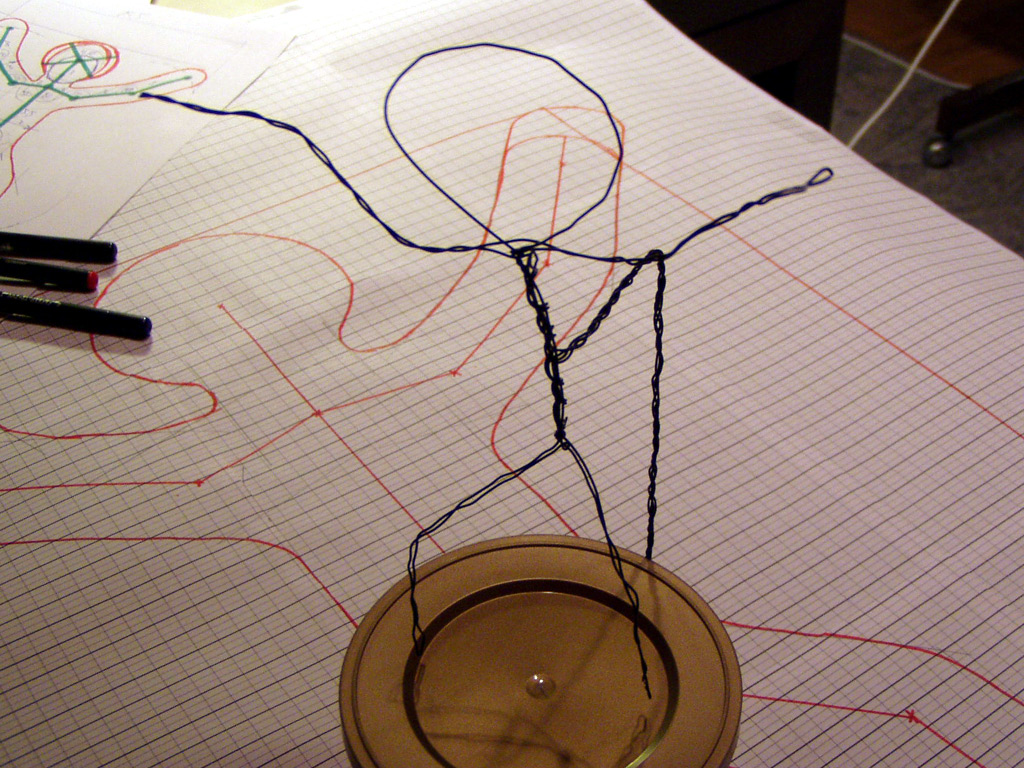
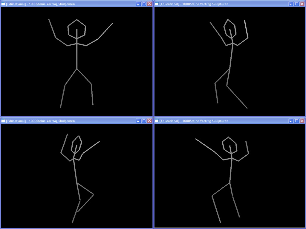
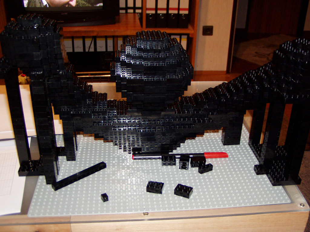
The side view is somewhat more complicated. To visualize the sculpture in 3D, models made from wire or computer generated 3D models (e.g. made with OpenGL) can be used. Both approaches allow one to experiment with the different angles of individual joints until the sculpture has the desired pose. Now, the side view can also be drawn on brick paper.
 |
 |
 |
As known from the sphere, the center lines are now drawn into the front and side view (one axis per individual object, such as arms, legs, torso, and head). Afterwards, the top view of each brick layer can be created. Once again, the middle lines are drawn and the distance from it to the front, back, left and right are plotted (simply count the studs based on the front and side view). These markings are connected to the ideal line and the best approximation to it must be found using the grid of the paper. To simplify the construction of the final sculpture, the outer line of the underlying brick layer should be transferred to the instruction for every new brick layer.
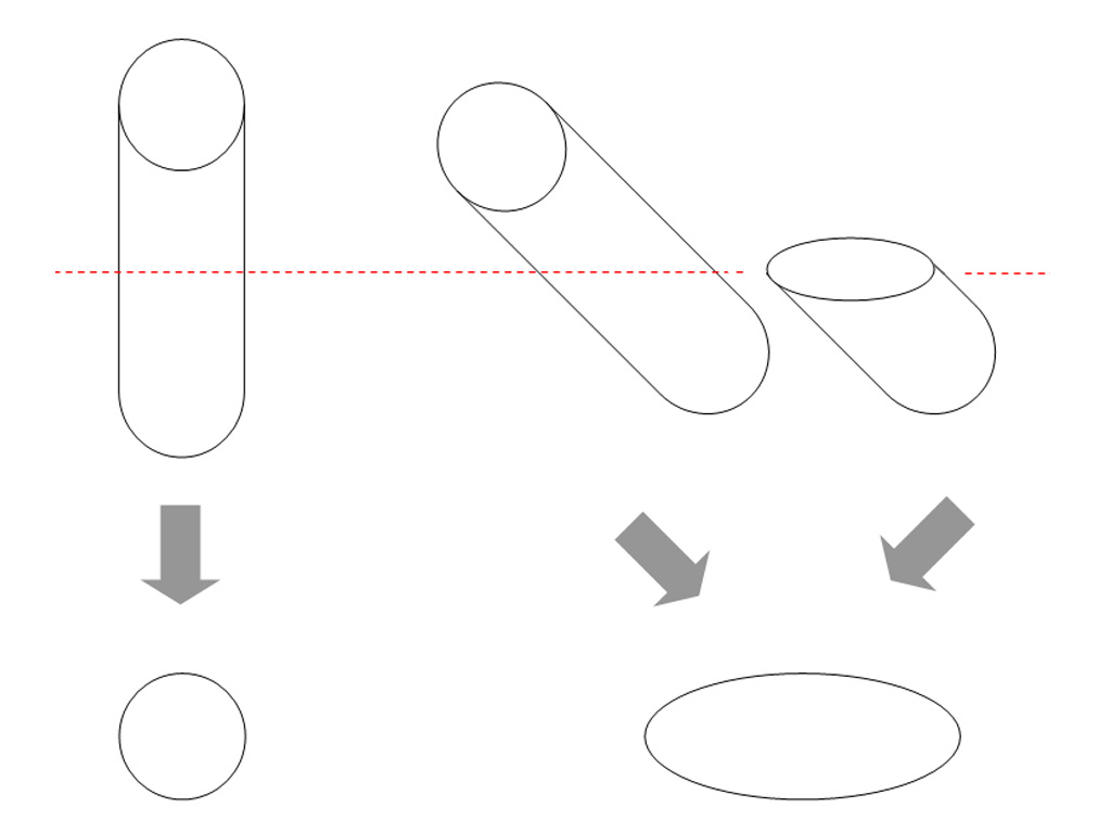
The top view of layer #47 is shown below to illustrate a more complex example. Is it a layer from the neck, containing both arms/shoulders. Here, the ideal lines are not circles but rather ellipses. This is due to the angle of inclination of the cylinders of both arms, since oblique cuts through a cylinder have an ellipsoid shape. Yet, also such shapes can easily be drawn by hand.
 |
 |
 |
Once all the top views are finished, the sculpture can be constructed. Please pay attention to:
 |
 |
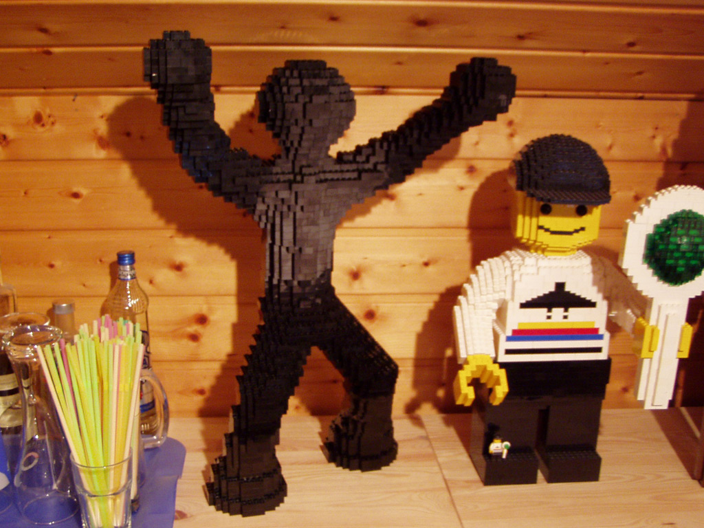 |
I hope the insight on my personal approach to building sculptures from Lego bricks will help you to create your own. I would be happy to be able to admire more such sculptures on the internet or at exhibitions in the future.
Last modified on 2009/11/29 - Copyright 2000-2021 - Tobias Reichling
XHTML 1.0 Validator, CSS Validator, optimal representation in Mozilla Firefox